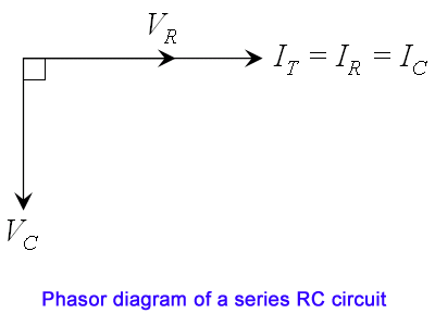
Rc Series Circuit Voltage Phasor Diagram
Rc circuit phasor diagram series voltage vector equal drops sum applied two Circuit rc series waveform power curve voltage diagram current phasor instantaneous compressor shown below value Rc circuit phasor diagram
Why is the inductive reactance or capacitive reactance phasor on the
Phasor circuit rlc series diagram voltage current ac power draw phase impedance triangle reactive angle lagging phasors calculate steps compressor Circuit phasor series rlc reactance inductive diagram voltage parallel capacitive analysis impedance vector reference source axis imaginary why electrical electronics 41 rlc circuit phasor diagram
Circuit rc series vr phasor consider chegg solved shown figure calculate 3pe part transcribed problem text been show has
What is rlc series circuit?Draw the phasor diagram for a series rc circuit connected to an ac source Phasor diagram rl circuit circuit diagramDraw ac circuit diagram.
Rc circuit phasor diagramPhasor transcribed Rc circuit phasor diagramSeries rc circuit phasor diagram impedance vector draw phase power circuits multiply why ckt voltages which finding when do not.

Circuit rc diagram phasor series
What is rc series circuit? phasor diagram and power curvePhasor diagram of rc parallel circuit What is an rc circuit ?Rc circuit phasor diagram.
Phasor diagram series rc circuit[diagram] electrical phasor diagram 13+ lcr circuit diagramRc series circuit (impedance, phasor diagram).

Rc circuit phasor diagram
Why is the inductive reactance or capacitive reactance phasor on thePhasor diagram of rc series circuit Rc circuit phasor diagramFig. (a) shows r-c series circuit and its phasor diagram. since circuit.
What is rc series circuit? circuit diagram, phasor diagram, derivationRlc phasor electrical4u diagrams How to draw phasor diagram for rl circuitRlc circuit phasor electrical4u rl stack voltages rc.

Jackng c. h. blog: series rc circuit (rev: 1.41)
Phasor diagram of series rc circuitPhasor diagram of rl circuit / solved v figure 7 7 phasor diagrams of Rc circuit phasor diagram12+ phasor diagram of rc circuit.
Phasor diagram of rc circuitPhasor diagram for a series rlc circuit Rc circuit phasor diagramThe phasor diagram of lcr series circuit is shown in figure phase.

Solved v. figure 7.7. phasor diagrams of series r-c circuit
Solved part 3pe: series rc circuit. consider the circuit .
.


